| Автор |
Сообщение |
|
|
Дата: 27 Окт 2008 23:55:26 · Поправил: Сергей (28 Окт 2008 00:17:35)
#
Passive Doppler Direction Finding
PlanePlotter uses a unique passive doppler direction finding method that uses the PC and its soundcard to generate and process the signals that are required for determining the direction of any incoming aircraft transmission.
As well as the PC and the receiver, you also need a simple antenna switch that is based on four PIN diodes. This inexpensive design (described below) requires no external power and can be built by anyone with basic electronics workshop skills.
Theory of Operation
The antenna multiplexer switches the receiver antenna connection successively between four sense verticals (dipoles or quarter-wave antennas) that are spaced approximately 0.2 wavelengths apart in a square pattern. The sense dipoles can be simple vertical half-wave dipoles or they can be quarter wave verticals as shown below. In the latter case, some adequate ground reference or balancing stub should be included to prevent common mode signals on the coaxial leads that connect to the antenna switch. The length and spacing of the sense elements is not critical so the system can be used over a reasonable band of frequencies.
http://photofile.ru/photo/aviation/115232026/122190227.jpg
The rapid switching of the antennas in sequence is equivalent to a single sense dipole that is rotating about a vertical axis at the switching frequency. The pseudo rotation of the sense dipole imposes a frequency modulation on the incoming signal whose phase, with respect to the switching waveform, is dependent on the direction from which the signal comes. The receiver is tuned to the wanted communications channel but in FM mode (although aeronautical communications are conventionally AM) so that the frequency modulation that is imposed on the incoming signal becomes an audio tone that is sent to the PC/laptop sound card. PlanePlotter compares the received signal with the switching waveform and computes the direction from which the signal is coming. This is then plotted on the chart as a radial line extending from your location.
The two audio channels from the PC/laptop speaker output jack are driven by the PlanePlotter software to provide two, maximum-amplitude, sinusoidal audio signals that are in quadrature (90 degrees phase angle apart). Each speaker channel drives two opposing switching diodes such that one antenna is connected through the conducting diode during one half cycle of each sinusoid and the opposite antenna is connected during the other half cycle. Since the two channels are in quadrature, the effect is similar to a rotary switch that is rotating around the four inputs from the sense antennas very rapidly.
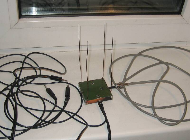
Antenna switch construction and description
The antenna switch is housed in a small diecast box.
On the outside are five Type-F coaxial connectors (for four sense dipoles plus the antenna lead to the receiver) and two feed-through capacitors (carrying the signals from the PC/laptop soundcard speaker output that are driving the switching diodes). The feedthough capacitors prevent any RF interference from entering the diecast box and transferring to the antenna signals.
http://photofile.ru/photo/aviation/115232026/122190235.jpg
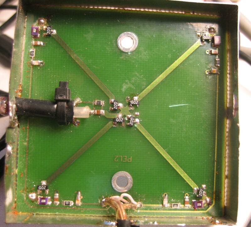
Internally there are five isolating capacitors and five isolating inductors (one for each coaxial connector) and four PIN diodes which are the actual signal switches connecting the four sense inputs in turn to the output to the receiver.
http://photofile.ru/photo/aviation/115232026/122190241.jpg
Each coaxial connection is connected through a ceramic capacitor (red in the photograph) that provides connectivity at RF but isolation to the audio frequency switching signals. The inboard end of each isolating capacitor is connected to one of the pin diodes and to an inductor (black) that provides connectivity at the audio frequency but isolation at RF. The inductors on the four sense inputs are connected to the signals coming through the two feedthrough capacitors. The inductor on the central, output, coaxial connector is connected to ground to provide a dc path for the switching currents.
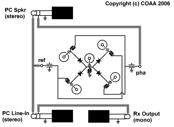
The audio signals to and from the PC/laptop and the receiver should employ screened audio leads and should be wired in accordance with the circuit diagram below. There are two coaxial 3.5mm stereo jack plugs that connect to the PC/Laptop Speaker Output and Line In respectively, and one 3.5mm mono jack plug that connects to the audio output of the receiver.
The arrangement and orientation of the diodes and the connection order from the feedthoughs inside the diecast box is critical and should be copied exactly.
Note that the Speaker output jack plug tip is wired to the reference input feedthough on the antenna switch (blue wiring internally in the photo) and also to the Line-In jack tip. This provides the reference signal with which PlanePlotter compares the phase of the audio signal coming from the receiver.
The Speaker output jack plug ring is wired only to the phase input feedthrough (yellow wiring internally in the photo) on the antenna switch.
The receiver audio output jack (mono) tip is connected to the Line In jack plug ring.
The screen of all the jack plugs connects to the screens of the audio leads and to the case (feedthrough outer bodies) of the antenna switch.
In order to preserve symmetry in the way the signals are processed, the layout inside the box should be as symmetrical as possible – especially with respect to the RF signal paths. The wiring between the feedthrough capacitors and the ‘cold’ ends of the isolating inductors is less critical.
The exact orientation of the four sense antennas with respect to N,S,E,W for example is not critical because in any case, the audio circuitry of the receiver imposes an unknown phase shift on the demodulated FM signal. For this reason, PlanePlotter includes calibration parameters that can accommodate any orientation of the antenna quartet. It must, of course, be constant. If used in a mobile environment, the calibration must be repeated each time the vehicle is repositioned.
Parts list
All part numbers in brackets are taken from the Farnell Electronics catalogue (www.farnell.com).
Precise component values may be not be critical. It may be possible to substitute similar types/values.
1 off Diecast box – (301-504)
5 off Type-F panel mounting sockets – (150-686)
2 off Feedthrough capacitors – (106-774)
5 off 1nF ceramic capacitors – (356-3479)
5 off 470 uH inductors – (517-070)
4 off 5082-3081 PIN diodes – (367-680)
2 off 3.5mm stereo jack plugs
1 off 3.5mm mono jack plug
screened audio cable as required
These are suggested components only and no warranty is given that they are suitable for the task.
Testing the system
Plane Plotter provides a number of ways to test and commission the direction finding system.
Testing the PC/laptop audio system
The audio output and input operation can be tested without an antenna switch.
Double click on the volume control icon on the system tray (bottom right corner of the desktop) to display the playback mixer dialog. Select the Wave source and move the slider to maximum. If there is a common volume slider at the left hand end, move that to maximum. If there is a physical volume control on the machine, move that to maximum.
Run PlanePlotter and select Options..Diredction finding..DF setup. Enter your home location latitude and longitude and leave the other values at their defaults. Click OK.
Select the Options..IO settings dialog. Disable other input options and enable the Direction finding option. Click OK.
Start processing (Process..Start).
You should now be hearing a fairly intense 3kHz tone though the speakers. This two-phase tone is the control signal for the antenna switch.
Connect a normal 3.5mm stereo jack extension lead directly from the speaker output of the PC soundcard to the Line-In input on the same soundcard. This should isolate the speaker so you no longer hear the piercing tone.
Select View..Signal.
Select Options..Audio..DF..Mixer. In the recording mixer dialog, select the Line In option. Looking at the signal display, adjust the slider in the mixer dialog so that the signals on the second and third line are smooth sinusoids and are not clipping. You should see that they are in quadrature (90 degrees out of phase) such that the peak on one corresponds to the zero crossing of the other. They should also be of the same amplitude. If they are not, the balance sliders of the Line-In mixer may not be centred.
Select View..Chart. Load a chart that covers your home location. You should see an orange symbol over you location and an orange line that extends in some direction from your location to the edge of the chart. This direction represents the phase difference between the generated tones (from the speaker socket) and the signals coming in to the Line-In socket.
With the process still running, select Options..Direction finding..DF test. This alters the relative phase of the generated tones to simulate the effect of signals from different directions. It should step around 10 degrees at a time at one second intervals. After 36 seconds it should be back where it started. Make sure that the steps are all uniform around the circle. If not, your sound card may be leaking the left and right channels in the speaker output.
Testing the antenna switch
Connect the PC speaker output jack, the PC Line-In jack and the receiver audio output as shown in the circuit diagram of the antenna switch but without connecting any antennas at this stage. Connect only the central output connector from the antenna switch to the antenna input of the receiver. Tune the receiver to a convenient continuous carrier signal (eg a volmet transmission). Set the receiver to AM mode (This is not how it would normally be used for direction finding but is required for this test).
Connect a single antenna to one of the four inputs on the antenna switch. On the chart display, you should see an orange radial vector in some direction. Disconnect the antenna from that input and re-connect it to the next input round the switch. The orange radial line on the chart should now be pointed at 90 degrees to the original direction. Repeat this for each of the four inputs and in each case, the orange line should step around 90 degrees each time. If this is so, then the antenna switch is working correctly.
Explanation
With only one input connected, the antenna switch is effectively an amplitude modulator of the incoming RF signal. Because the driving signals are in quadrature, the four inputs are connected cyclically and the peak amplitude occurs at different points in the driving cycle for each of the four inputs. Using the receiver in AM mode delivers that amplitude modulation to the audio input. PlanePlotter determines the phase of the signal and the displayed vector should match the sequence of the four inputs.
Normal operation
Connect the PC speaker output jack, the PC Line-In jack and the receiver audio output as shown in the circuit diagram of the antenna switch. Connect the four sense antennas to the four inputs of the antenna switch and connect the central output connector to the antenna connector of the receiver. Tune the receiver to the wanted communications channel and set it to FM mode.
You may find it convenient to have a second receiver on the same channel tuned to AM mode and audible in a loud speaker in order to interpret what you see.
Set up your home location as described above and start PlanePlotter processing with the DF option enabled.
Whenever a signal is received, the orange vector should appear on the chart radiating from your home location.
Because the antenna array may have any orientation and because the phase change in the receiver signal path cannot be predicted, you must determine the calibration necessary to make the orange vector point correctly towards the signal source. In the Options..Direction finding..DF setup dialog, increasing the Azimuth offset value will rotate the vector clockwise by that number of degrees.
If you have constructed the antenna switch in accordance with the circuit diagram and photographs, and if the switch is used with the input connectors on the top, as shown in the earlier photograph, then the display vector will move in the correct sense. If you have reversed a pair of diodes, installed the switch upside down (connectors on the bottom), or if the soundcard left and right channels are somehow swapped over, then you will need to check the Reverse rotation option in the Options..Direction finding..DF setup dialog.
Cautions
There are some points to be aware of. Precise tuning is essential. If the signal is off tune, the transfer function of the FM demodulator on the receiver may be working on the outside slope of its transfer function and this will reverse the observed phase of the audio signal. This will cause the vector that PlanePlotter displays, to be in completely the wrong direction. Aircraft are generally on the nominal frequency. Some ground stations may not be. Specifically, some administrations use frequency offsets (usually by 6kHz) to obtain wide area coverage with multiple base stations. If you are tuned to the nominal frequency but are receiving the ground signal from such an offset station, it is highly likely that your receiver demodulator will be working on the outside slope of its response curve and the result will be wrong. If you need a calibration signal, a local tower or ATIS frequency may be more likely to be tuned to the nominal frequency than an area (“Control”) or wide area (“Volmet”) signal. |
|
|
Дата: 28 Окт 2008 00:16:57 · Поправил: Сергей (28 Окт 2008 00:18:08)
#
You can sometimes discover frequency offsets using USB or LSB mode and listening for a heterodyne.
The PlanePlotter DF system determines the direction from which the incoming signal arrives at the antenna quartet. If the antenna is not well clear of obstructions (trees, buildings, other antennas), it is possible that the signal will arrive at the antenna quartet by reflection and so display a misleading direction on the chart. Professional DF installations are always well away from other obstructions.
|
|
|
Дата: 28 Окт 2008 00:57:34 · Поправил: censored_dream (28 Окт 2008 00:59:05)
#
Ни разу не бред, вполне все понятно написано.
Система состоит из обычного приемника на авиачастоты и четырех антенн, по очереди коммутируемых пин-диодами ко входу приемника.
Управление пин-диодами производится двумя сигналами с выхода саунд-карты (стерео). Каждый сигнал коммутирует по две антенны (положительная полуволна - одна антенна, отрицательная - другая, близкое к 0 напряжение - обе антенны отключены).
Быстрое переключение антенн равносильно перемещению антенны в пространстве, что вызывает допплеровский сдвиг сигнала, фиксируемый приемником в режиме ЧМ.
Сигнал с приемника подается на вход саунд-карты. Компьютер ищет корреляцию этого сигнала с сигналами, которыми управляется коммутатор, и вычисляет направление на источник.
|
|
|
Дата: 28 Окт 2008 10:09:33 · Поправил: candid (28 Окт 2008 13:15:47)
#
Если внимательно рассмотреть схему, то можно увидеть что сигнал с антенн идет не на вход "СаундБластера" а на вход радиоприемника.
На один канал "СаундБластера" идет выход с приемника, а на другой канал "СаундБластера" идет опорная частота 3 кГц которой коммутируют антенны.
Нарисовано конечно не по нашенски, но разобраться можно.
 |
|
|
Дата: 28 Окт 2008 10:36:15
#
F-разъёмы - это сильно!
Ну что ж, раз "работает" такое, значит, осталось повторить.
|
|
|
Дата: 24 Ноя 2008 22:45:57
#
|
|
|
Дата: 19 Май 2009 11:07:08
#
Кто-нибудь сможет дать ссылку на софт пеленгатора с Саунд-картой ?
|
|
|
Дата: 19 Май 2009 11:57:04
#
Slavik
http://www.coaa.co.uk/planeplotter.htm
PlanePlotter can drive a passive antenna switch and display the direction (QDM) of any aircraft voice transmission.
Отличная идея, как, впрочем, и все от COAA.
Звуковуха управляет диодами и переключает вход приемника по кругу между 4-мя антеннами. На вход звуковухи идет сигнал уже с выхода приемника, обрабатывается, после чего мы получаем направление на самолет. Дешево и изящно. Все устройство на схеме и в картинках. Руки зачесались... |
|
|
Дата: 19 Май 2009 14:04:49
#
|
|
|
Дата: 19 Май 2009 15:36:29
#
Чтобы этот пеленгатор работал, приемник настраивается в режим FM, а не AM. Так чтослушать переговоры придется на второй приемник.
|
|
|
Дата: 19 Май 2009 23:51:21
#
Сергей
Ну как, не надумал сделать такой аппарат? Или тебе уже за глаза ADS-B хватает? :)
|
|
|
Дата: 20 Май 2009 00:01:48
#
|
|
|
Дата: 15 Ноя 2009 17:48:22
#
А лучше реализовать и попробовать
Я как то и попробовал.
Для коммутатора использовал плату от своей старой конструкции.Единственное ,что пришлось перевернуть
пин-диоды в одной диагонали.Коммутация то синусом идёт.
Проверял для диапазона 433 мГц.Программа DF Plotter.
Работает и даже очень не плохо.Если конечно напряжение на пин-диодах правильно выставить и
симметрию обеспечить.
Скриншоты привести сейчас не могу ,так как 21 дневный пробный срок кончился давно,а лекарства нет. |
|
|
Дата: 15 Ноя 2009 18:59:13
#
и пр... когда нашу часть разведки перевозили с Кубы, а точней её имещество в 2001 или 2002 году на Чкаловский сам лично слушал наш борт над Канадой. А так - здорово, когда в Твоём распоряжении ТАКОЙ антенный комплекс, что правктически все могут позавидовать. Ну и плюс спутники брали )
Осень, сказочники из под листвы поперли ;)))))
|
|
|
Дата: 15 Ноя 2009 19:40:09
#
john_qkk
получается, для каждой новой частоты необходимо настраивать коммутатор?
|
|
|
Дата: 15 Ноя 2009 19:43:12
#
получается, для каждой новой частоты необходимо настраивать коммутатор?
Не надо.
|
|
|
Дата: 15 Ноя 2009 20:07:13
#
Maxwel
а расстояние между антеннами критично?
нужно ли его изменять в зависимости от пеленгуемой частоты?
|
|
|
Дата: 15 Ноя 2009 21:26:57
#
BATONS
Расстояние между антеннами в пределах 1/8L -1/4L.
|
|
|
Дата: 16 Ноя 2009 19:36:33
#
Maxwel
Расстояние между антеннами в пределах 1/8L -1/4L.
спасибо. как нибудь попробую эту конструкцию. А вы какие пин-диоды использовали?
|
|
|
Дата: 16 Ноя 2009 19:51:09
#
|
|
|
Дата: 16 Ноя 2009 21:01:42 · Поправил: john_qkk (16 Ноя 2009 21:42:04)
#
Maxwel
Скриншоты привести сейчас не могу ,так как 21 дневный пробный срок кончился давно,а лекарства нет.
А чем генератор ключей для PlanePlotter, что я отправлял ранее не нравится?:
Портативный радиопеленгатор для авиационного диапазона - Страница 2
Да, вируса там нет. Касперский пропускает и не придирается. Только что проверил.
Последня версия PlanePlotter'а 5_4_4_2 с официального сайта вполне даже работает со сделанным ключом. |
|
|
Дата: 16 Ноя 2009 22:31:53
#
john_qkk
А чем генератор ключей для PlanePlotter, что я отправлял ранее не нравится?: Не
Вот тут то какая то засада. Не работает (во всяком случае у меня) PlanePlotter в режиме пеленгатора.
Проверял обе последних версии на трёх компьютерах.
Последня версия PlanePlotter'а 5_4_4_2 с официального сайта вполне даже работает со сделанным ключом.
А как вы проверяли работоспособность? При актавации режима пеленга с выхода звуковой карты должно
3000 гц звучать. Так оно и было в DF Plotter .
Жаль что на DF Plotter время кончилось. Переустановка не помогает. И где автор счётчик дней спрятал ? Ни одним деинстолятором не могу найти и лекарства нет.
|
|
|
Дата: 25 Ноя 2009 21:04:48 · Поправил: john_qkk (25 Ноя 2009 21:07:46)
#
Maxwel
Там есть хитрость, ее надо вычитать в описании (содержание - tutorials - direction finding with PlanePlotter).
Идем в options - i/o settings
Там в разделе input data надо снять галочки со _всех_ квадратиков кроме direction finding from sound input.
Далее жмем process - start
Только что проверил и чуть не оглох с этого звука.
Версия 5.3.6.1, ранее проверял на 5.4.4.2
|
|
|
Дата: 25 Ноя 2009 21:08:41
#
Жаль что на DF Plotter время кончилось. Переустановка не помогает. И где автор счётчик дней спрятал ? Ни одним деинстолятором не могу найти и лекарства нет.
Думаю, там все по-старинке и все должно лечиться убиением одной строчки в реестре.
|
|
|
Дата: 27 Ноя 2009 00:22:54
#
Вот отличный "наборчик" и не дорого вроде... |
|
|
Дата: 27 Ноя 2009 09:42:10
#
|
|
|
Дата: 27 Ноя 2009 10:01:00
#
Не всё так просто .Файл не обязательно прячется в реестре.
Надо было конечно до установки сделать "снимок" системы ,тогда было бы легче.
Попробуйте установите программу и подскажите что надо убить.
Я не большой специалист в этих делах.
А в принцыпе это уже не нужно.
Спасибо john_qkk PlanePlotter заработала ,а она в части пеленгации
не отличается от DF Plotter.
|
|
|
Дата: 27 Ноя 2009 15:17:32
#
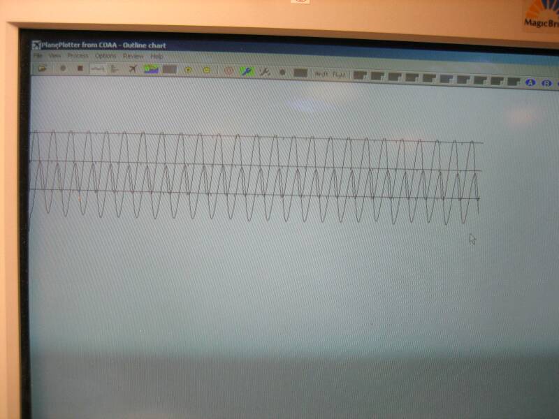
Сигнал с выхода зв.карты и с нч. выхода приёмника.
Виден фазовый сдвиг который меняется в зависимости от
направления пелегуемого сигнала.
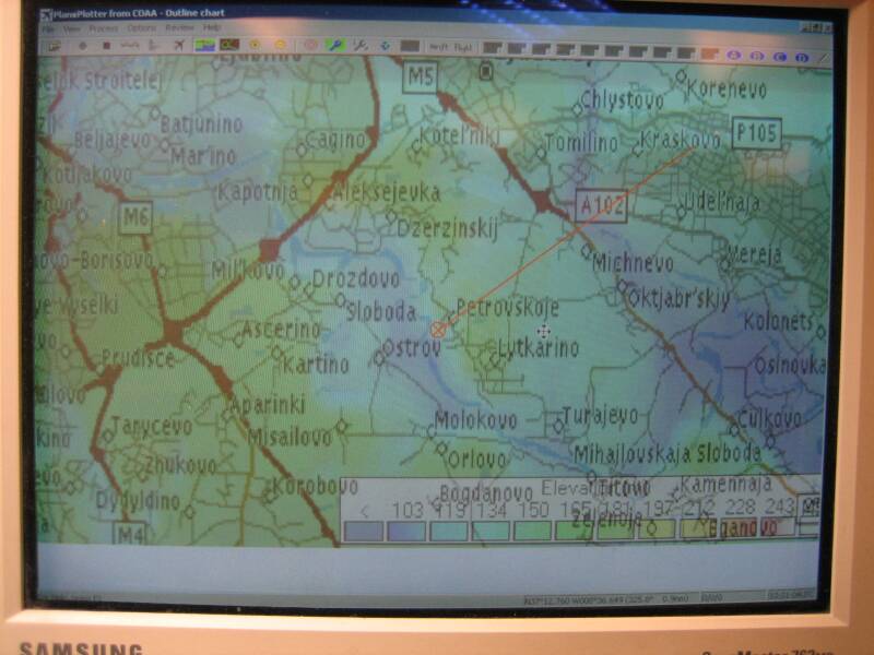
А вот собственно как пеленг отображается.
Карту я подставил первую попавшеесю и точку на карте тоже .
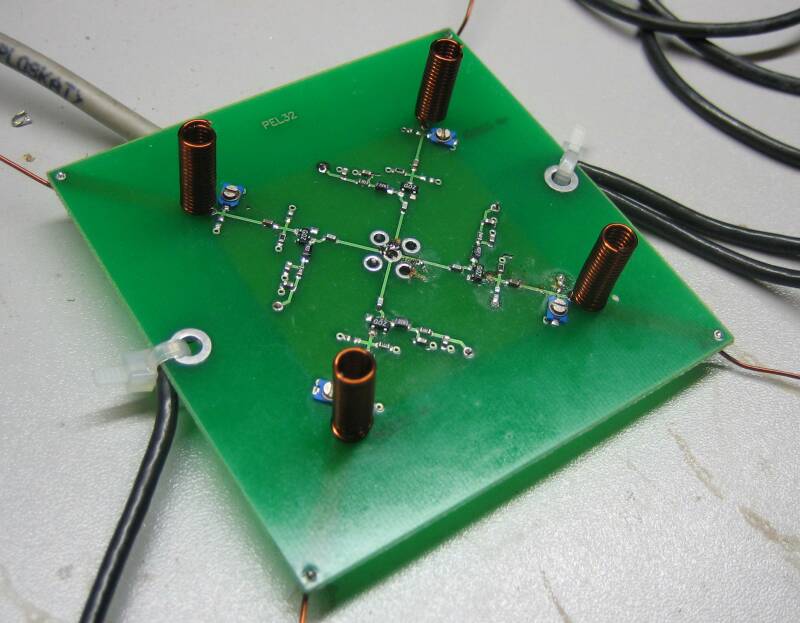
Ну а это сам коммутатор (так же от своей старой конструкции) .
Такие антеннки конечно можно использовать только для демонстрации.
 |
ASHУчастник
 
с сен 2006
Жуковский (ko95bo), RN3DAS
Сообщений: 2986
|
Дата: 01 Фев 2010 22:54:53 · Поправил: ASH (01 Фев 2010 22:56:04)
#
Уфф, вроде получилось повторить конструкцию. Диоды взял BAR63, в Чип и Дипе по 18 рублей.
Пока проверял только в помещении и на 70-ке, синусоиды правда не такие ровные, как у Maxwel, но стрелочка за радиостанцией перемещаться пытается, хотя прыгает конечно (что и понятно - переотражений полно). Ну и по тесту антенного переключателя из Хелпа тоже похоже на правду получается..
Нужно теперь на открытом пространстве потестировать..
При настройке и тесте нужно следовать советам из Хелпа к программе, там написано, как выставлять уровни на регуляторах громкости.
|
|
|
Дата: 01 Фев 2010 23:08:08
#
А фото реализации можно?
|